|
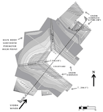
The three northeast secondary roofs have the same shape, construction and material as the south-west secondary roofs. All these northeast roofs are in the lee of the right leg of the high main roof and are in afternoon shade.
At the northernmost northeast roof, the predicted snow distribution is the least at the roof's high point (under the main high roof) and the most at the eave. Additionally, wind drift accumulations will form and build up near the middle of this lower roof due to its being sheltered by the high main roof from both wind and afternoon sun. A snow cornice condi-tion will also occur at the eave.
The small, narrow northeast center roof will have a similar snow distribution pattern as its northern neighbor. The snow accumulation will be deeper and a snow cornice will form at the eave due to being bound by walls on the other three sides.
The southernmost northeast secondary roof is pitched both northeast and southeast with a valley at the intersection. The southeastern-pitched roof surface will have some additional sun exposure. Snow distribution will be the least under the high main roof. The most snow buildup will be at the base of the valley and then along the eave of the northeast pitched section. Wind drift snow (from the high roof) will add to the eave accumulations. A snow cornice condition will also form at the eave, with the most buildup at the end of the valley.
All these northeastern low secondary roofs, behind the main high roof, will receive virtually no sun in midwinter and the southwest wind will drift all of the stripped snow from the high roofs onto them.
3. Snow Cornices
In general, the metal standing rib cold roof and low roof pitch will only allow the snow mass to gradually creep down over the eaves. Metal ribs tend to hold snow as well as channel it. When the right conditions occur, the cantilevered snow cornice will calve off the eave, falling onto the ground below. Over time, this will build up a snow berm. Under certain heavy conditions, the snow berm will build up high enough to stop sliding/creep movement of the roof snow. This situation will most likely occur in the western corner area of the courtyard because of its very wind and sun-sheltered location. The case study design will incorporate a below-grade snowmelt system to mitigate courtyard snow removal needs. Other places that these snow cornice conditions will probably occur will most likely be at the northeast secondary roof eaves.
SUMMARY
The bottom of the main roof valley at the west corner of the courtyard is estimated to have 3 M (10 ft.) of snow with at least 30% density. This translates to approximately 9.28 kN/m2 (190 lb/ft2), almost double the design snow load. Eave loading due to snow cornice cantilevers approach four times the design snow loads. At 30% density, snow depths of 1.65 M (5'4") or above exceed the design snow load of 4.93 kN/m2 (101 lb/ft2). Roof snow depths, snow density and snow cornice conditions will be at maximums. (Figure 7).
|


