|
Two valleys are formed where the three main roof sections intersect. The roof structure is designed as a "cold" well-ventilated roof with 23 cm (9") of outside airflow ventilation space (Mackinlay, Flood3). The roofing material is a standing seam metal roof with flat seamed valley sections that progressively widen on the slope down to the eaves. The eave-to-high point distance varies because of the sawtooth perimeter. The distance ranges between 14.6 m (48 ft.) to 32.9 m (108 ft).
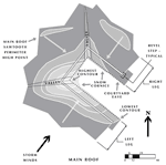
Empirically taking into account the southwest wind drift propensity of the site, the sawtooth outer perimeter of the main roof, its shallow bowl shape and some initial field snow sliding, snow depth contour lines are then plotted. This results in an estimated topographic snow distribution mass. (Figure 4A).
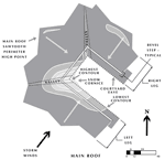
With some passage of time and some above-freezing temperatures, it is predicted that the initial snow distribution mass will, under the factors of wind, sun, and gravity, consolidate and shift to a new estimated position (Figure 4B).
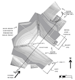
When these multiple cycles of intense storms and freeze/thaw conditions occur in heavy snow seasons, the snow layering techniques of figures 4A and 4B build up. In late March or early April, it is estimated that maximum roof snow distribution and depth will occur. (Figures 5, 6).
In general, maximum roof snow depth will occur along the eave of the left (southwest) leg of the main roof, due to drifting and being in the lee of the wind. This lee side also has the least afternoon sun exposure. The highest snow build-up should occur at the base of the valley between the left main roof leg and center section. Here the wind patterns should create the most favorable conditions for deep snowdrifts to occur.
Because of the bowl shape of the main roof "U", the areas on the upper roof should be fairly devoid of snow due to wind stripping and scouring. Snow accumulation on the right leg and right center section eaves will be less due to being on the windward side of the bowl and having afternoon sun exposure.
Furthermore, over time, the roof snow will have consolidated and may exceed 30% water content. Eave snow cornice conditions may exceed 50% water content due to the usual ice layer at the inside cornice surface.
2. Secondary Roofs (Figure 3)
The two secondary southwest 2:12-pitch sloping shed roofs on the left (outer) side of the project face directly into the wind and storm track. The high points of these roofs abut vertical exterior walls of the main building "U" form. A portion of the main "high" roof cantilevers out over the top of these ex-terior walls and partially shelters the secondary roofs below. These secondary roofs are covered with standing seam metal panels and are also designed to be well-ventilated "cold"3 roofs. Both of these southwest sloping roofs are on the windward side and face afternoon sun.
It is estimated that snowfall drifted by wind will form the highest snow accumulations more or less in the middle of the slope as well as inside wall corner pockets. This snowdrift profile has been assumed due to the wind deflection/vortex action in the "pocket" formed by the low secondary roof, exterior wall, and soffit of the high main roof. (Figures 5, 6).
|


